Hardware overview (IFP52-1C)
Welcome to ViewBoard and your newly acquired interactive flat panel (IFP). Your ViewBoard IFP52-1C series comes with various components to assist in connecting devices and enhance your usage of the ViewBoard.
This article introduces the basics of the IFP52-1C's additional hardware, as well as gives an overview of the display's control panel and ports.
Equipment basics
The following items are included in your IFP52's packaging:
What comes with your ViewBoard
 Pen stylus (2x) Pen stylus (2x)
|
 Eraser Eraser
|
 Remote control Remote control
|
 AAA batteries (2x) AAA batteries (2x)
|
 RS-232 adapter RS-232 adapter
|
 Power cord Power cord
|
 HDMI cable (15ft/3m) HDMI cable (15ft/3m)
|
 USB Type-C cable (5ft/1.5m) USB Type-C cable (5ft/1.5m)
|
USB cable for touch (15ft/3m)
|
 Clamp (5x) Clamp (5x)
|
 Webcam plate Webcam plate
|
 Webcam screws Webcam screws(M4 x 6mm 2x; M3 x 6mm 2x) |
 Wall mount screws Wall mount screws(4x M8 x 25mm) |
 Quick start guide Quick start guide
|
 Compliance statement Compliance statement
|
Wall mount kit specifications (VESA specs)
The following are some specifications for wall mounting an IFP52-1C. For specific wall mount or mobile mount bracket installation steps, please review your IFP52-1C's Quick Start Guide wall mount installation guide. If attaching to other building materials, please contact your nearest dealer.
 Rear panel of a ViewBoard IFP52-1C with VESA spec measurements highlighted. Refer to the table below for corresponding measurements.
Model |
VESA Spec. (A x B) |
Standard Screw (C x D) |
Quantity |
|---|---|---|---|
| IFP6552-1C | 600 x 400 mm | M8 x 25 mm | 4 |
| IFP7552-1C | 800 x 400 mm | M8 x 25 mm | 4 |
| IFP8652-1C | 800 x 600 mm | M8 x 25 mm | 4 |
IFP52-1C controls and ports overview
This section breaks down the details of different input/out (I/O) ports and controls located on the IFP52-1C.
 Front panel of the IFP52-1C with input/output (I/O) ports and control panel areas highlighted.
 Rear panel of the IFP52-1C.
Control panel
The control panel, found on the bottom-right corner of the front of the IFP52-1C, contains basic commands for the device.
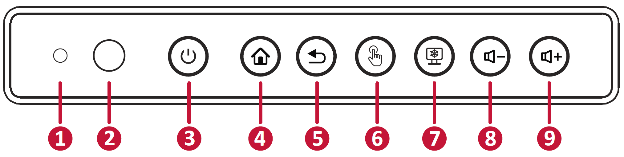 Refer to the table below for control panel details.
Function |
|
|---|---|
| 1 | Ambient Light Sensor: Monitor a room's ambient light. |
| 2 | Remote control receiver: Receives commands from the device's remote control. |
| 3 |
Power indicator light:
|
| 4 | Home: Return to the ViewBoard's home screen. |
| 5 | Return: Return to the ViewBoard's previous screen. |
| 6 | Touch lock: Disable/enable touch interaction. |
| 7 | Freeze: Lock the current image on the screen. |
| 8 | Decrease volume |
| 9 | Increase volume |
Input/output panels
Your IFP52-1C comes with multiple input/output (I/O) panels. The ports on these panels provide different ways to connect external devices by wire.
 Overview of I/O panels located on different parts of the device.
Port |
Function |
|
|---|---|---|
| 1 | USB Type-C |
|
| 2 | HDMI 1 |
|
| 3 | TOUCH 1 |
|
| 4 | USB 3.0 | Connect USB devices such as a hard drive disk, keyboard, mouse, etc. Automatically switches between PC and ViewBoard input sources. |
| 5 | OPS PC slot | Supports a standard Open Pluggable Specification PC module. |
| 6 | TOUCH 2 |
|
| 7 | HDMI 2 |
|
| 8 | HDMI 3 |
|
| 9 | HDMI 4 |
|
| 10 | TOUCH 3 |
|
| 11 | USB | For ViewBoard channel and ViewSonic motorized trolly use only. |
| 12 | AUDIO OUT | External computer audio input to a speaker/headset. |
| 13 | Wi-Fi slot | Compatible with LB-WIFI-001 and VB-WIFI-001, which are designed for ViewBoards and verified by ViewSonic. (Note: 3rd party or unverified dongles may not be compatible.) |
| 14 | HDMI OUT | Connect to devices with an HDMI input function. Supports 1080p and 4K@60Hz. |
| 15 | LAN | Standard RJ45 (10M/100M/1000M) Internet connection interface. This network port is used for the ViewBoard, Type-C, and slot-in PC input sources. |
| 16 | RS-232 | Serial interface; used for mutual transfer of data between devices. |
| 17 | VGA | External computer video input. |
| 18 | AUDIO IN | External computer audio input. |
| 19 | SPDIF | Multi-channel sound via optical signals. |