Hardware overview (VPC-A31-O1)
Welcome to ViewSonic VPC-A31-O1 Android EDLA (Enterprise Device Licensing Agreement) certified OPS (Open Pluggable Specification) device. Your VPC-A31-O1 slot-in device can be installed on any OPS-compliant display, including ViewBoards and CDEs.
This article introduces the basics of the VPC-A31-O1's hardware, as well as gives an overview of the display's ports and general uses.
What makes this device Android EDLA certified?
Google now provides a partner program with Android EDLA (Enterprise Device Licensing Agreement) certification for large panel displays. As an EDLA certified device, the VPC-A31-O1 has Google Mobile Services, or GMS, built-in. Altogether, this means all Google's most popular apps and services are supported right on the device.
Access Google Drive, Chrome, Docs, and more with all your files and settings configured after signing in to your device. Additionally, open the Google Play Store to browse all your preferred apps. View the Kids page where popular trusted apps for educators can be found. Rest assured that all apps downloaded to your system are safe and secure by checking Play Protect in your settings.
Learn more about Android EDLA certification.
Equipment basics
The following items are included in your A31-O1's packaging:
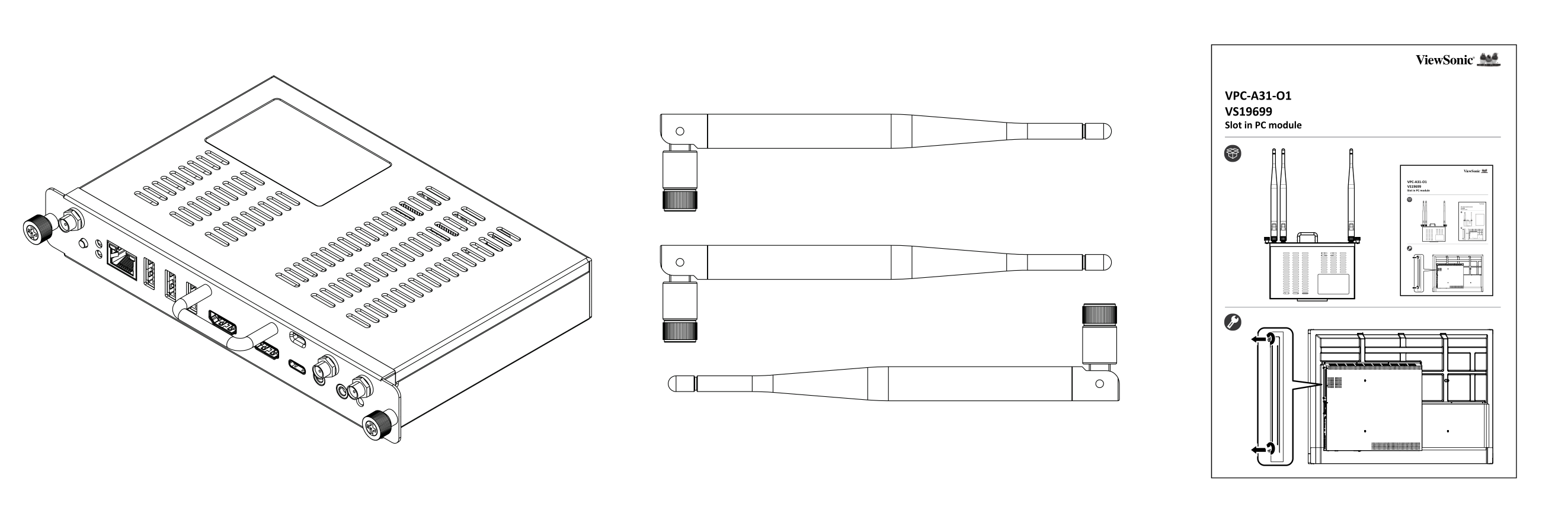
A31-O1 ports
This section breaks down the details of different ports and controls located on the A31-O1. These ports are also all accessible after slotting in the VPC.
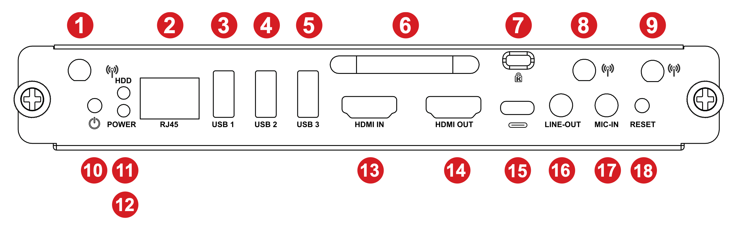 VPC input/output ports panel. Refer to the table below for function details.
Button/Port |
Function |
|
|---|---|---|
| 1 | Antenna | Wi-Fi antenna interface. |
| 2 | RJ45 | Standard RJ45 (10M/100M/1G) internet connection port. NOTE: This network port is only used for the PC. |
| 3 | USB 1 | USB 3.0 port. |
| 4 | USB 2 | USB 3.0 port. |
| 5 | USB 3 | USB 3.0 port. |
| 6 | Handle | Grab the handle when slotting the VPC in/out. |
| 7 | Security lock | Secure the device to a fixed object for increased security and safety. |
| 8 | Antenna | 2.4G antenna interface. |
| 9 | Antenna | Wi-Fi antenna interface. |
| 10 | Power button | Button for manually powering on the VPC. |
| 11 | Status LED | When the status indicator is always green, the VPC is running. |
| 12 | Power LED | When power indicator is flashing red, the VPC is powered ON. |
| 13 | HDMI IN | HDMI input for connecting an external PC or other device and displaying its contents through the VPC input source. |
| 14 | HDMI OUT | Output the VPC's screen to an external display. |
| 15 | USB Type-C | Data-only USB C input port; 5V/0.9A charging. |
| 16 | LINE-OUT | Audio out port to connect speakers or headphones. |
| 17 | MIC-IN | Port for connecting an external microphone. |
| 18 | Reset | Press to hard reset the VPC. |
Installing the A31-O1
The following instructions show you how to install the VPC onto your OPC-compatible display.
- Remove the slot-in PC cover from your display. (See image 1.)
- Holding the A31-O1's handle, carefully insert it into the PC slot. (See image 2.)
- Secure the A31-O1 in the slot with the 2 included screws.
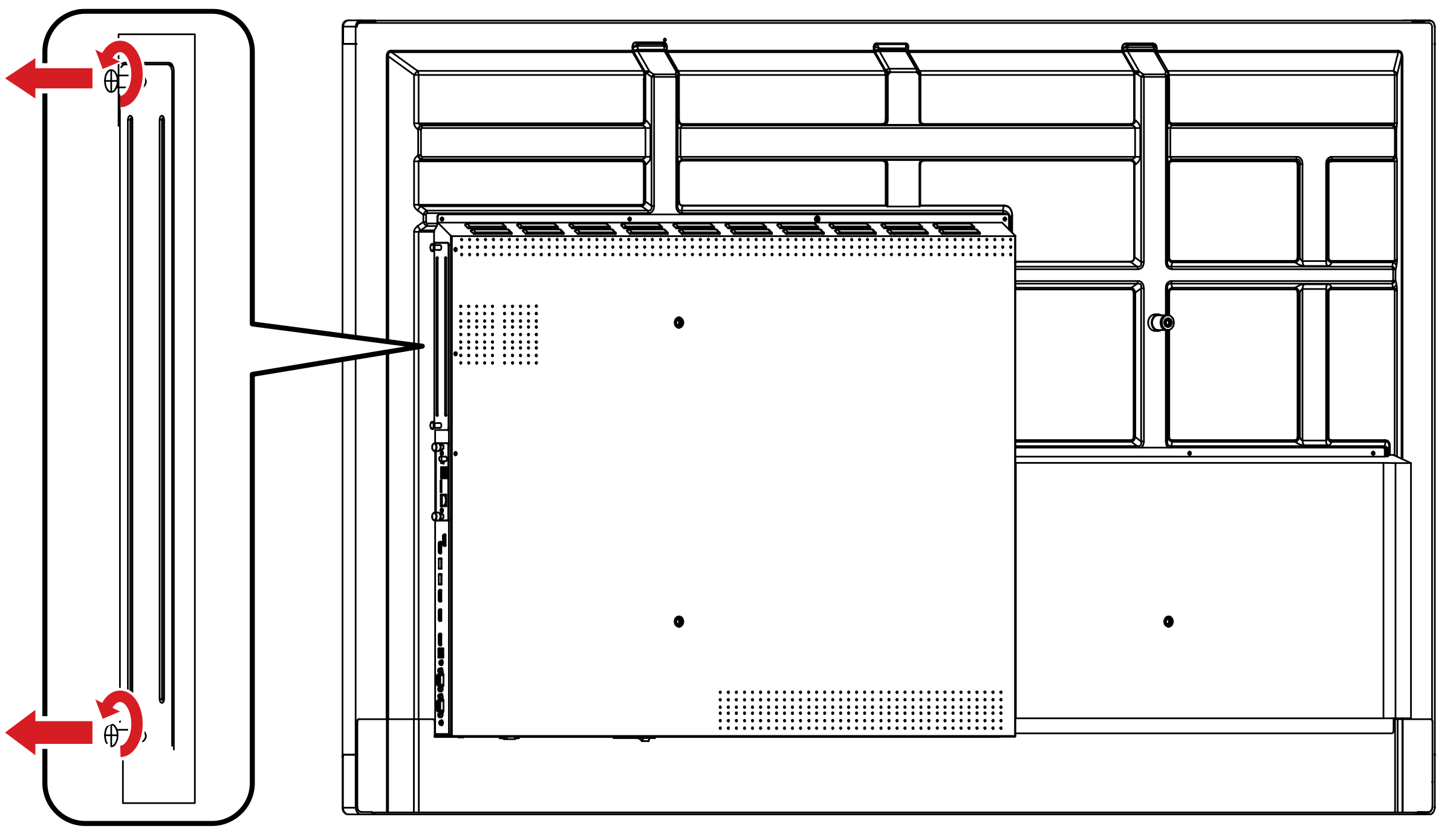 Image 1: Removal of slot-in cover with screw locations highlighted.
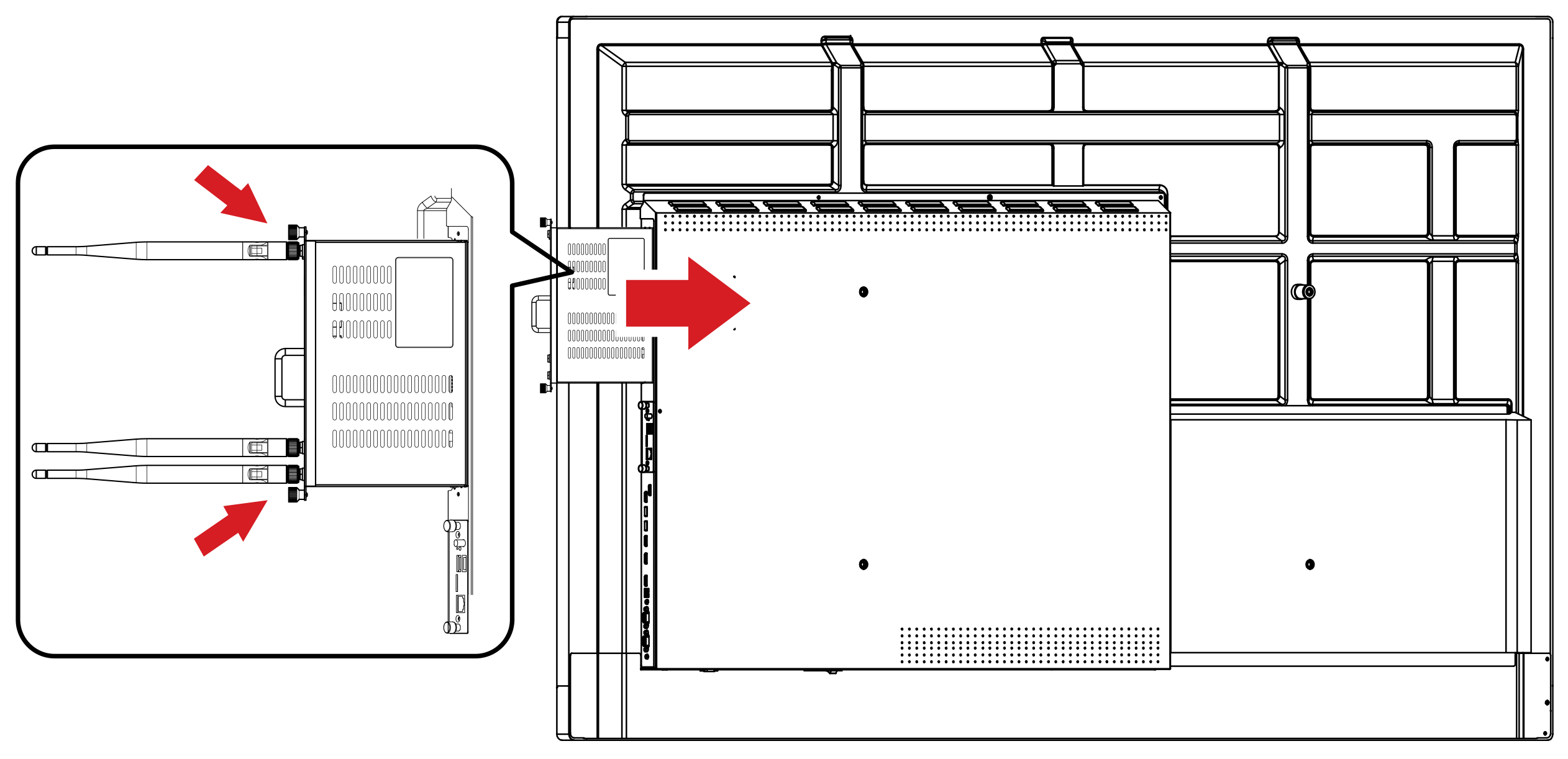 Image 2: VPC being slotted in with direction highlighted. (View from the back of an IFP.)