Vista previa del hardware de la serie IFP52
Bienvenido a ViewBoard y su pantalla plana interactiva (IFP) recién adquirida. Su serie ViewBoard IFP52 viene con varios componentes para ayudarlo a conectar dispositivos y mejorar su uso de ViewBoard .
Este artículo presenta los conceptos básicos del hardware adicional del IFP52 y brinda una descripción general del panel de control y los puertos de la pantalla.
Conceptos básicos del equipo
Los siguientes elementos están incluidos en el embalaje de su IFP52:
Qué viene con su ViewBoard
 Cable HDMI (10 pies/3 m) Cable HDMI (10 pies/3 m)
|
 Control remoto Control remoto
|
 Pilas AAA (2x) Pilas AAA (2x)
|
 Cable USB para pantalla táctil (10 pies/3 m) Cable USB para pantalla táctil (10 pies/3 m)
|
 Placa de cámara web Placa de cámara web
|
 Lápiz óptico (2x) Lápiz óptico (2x)
|
 Adaptador RS-232 Adaptador RS-232
|
 Cable USB tipo C (5 pies/1,5 m) Cable USB tipo C (5 pies/1,5 m)
|
 Abrazadera (5x) Abrazadera (5x)
|
 Borrador Borrador
|
 Tornillos de cámara web Tornillos de cámara web(4x: M4 x 7 mm 2x; M3 x 7 mm 2x) |
 Tornillos de montaje en pared Tornillos de montaje en pared(4x: M8 x 20 mm 4x) |
 Guía de inicio rápido Guía de inicio rápido
|
 Cable de alimentación Cable de alimentación
|
 Declaración de conformidad Declaración de conformidad
|
Especificaciones del kit de montaje en pared (especificaciones VESA)
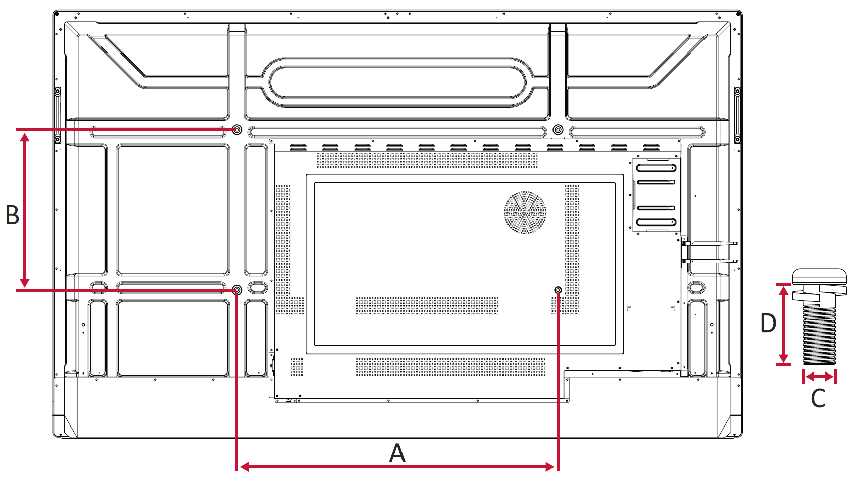
Aquí tienes algunas instrucciones para colocar una IFP52 en la pared. Para conocer los pasos detallados, consulta la guía de instalación en la Guía de inicio rápido de tu IFP52.

Modelo |
Especificaciones VESA. (AxB) |
Tornillo estándar (C x D) |
Cantidad |
|---|---|---|---|
| IFP6552 | 600 x 400 mm | M8x20mm | 4 |
| IFP7552 | 800 x 400 mm | M8x20mm | 4 |
| IFP8652 | 800 x 600 mm | M8x20mm | 4 |
Descripción general de controles y puertos IFP52
Esta sección desglosa los detalles de los diferentes controles y puertos de entrada/salida (E/S) ubicados en el IFP52.
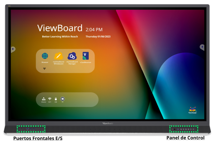
 Panel frontal del IFP52 con puertos de entrada/salida (E/S) y áreas del panel de control resaltadas.
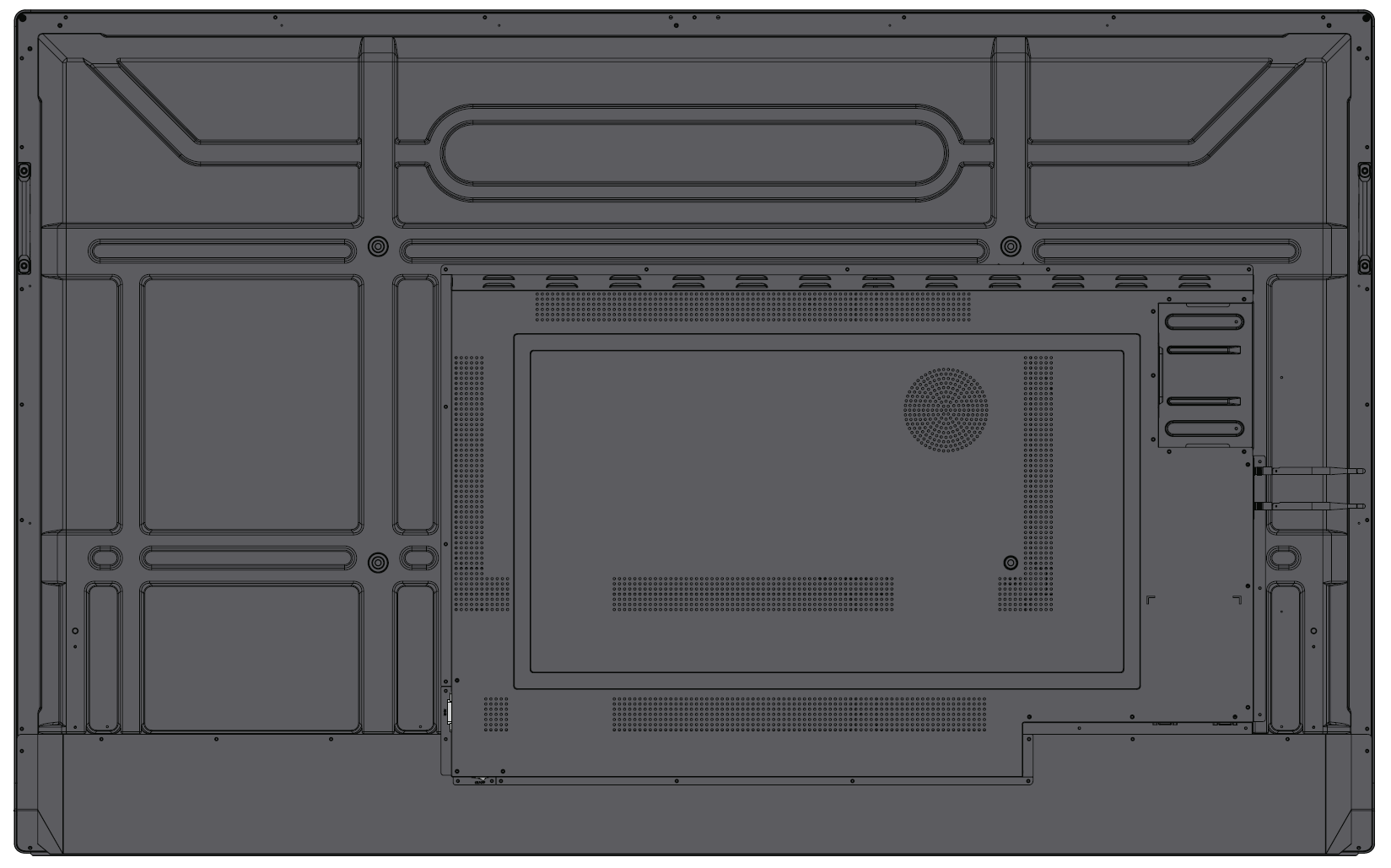
 Panel trasero de la IFP52.
Panel de control
El panel de control, que se encuentra en la esquina inferior derecha del frente del IFP52, contiene comandos básicos para el dispositivo.

|
Función |
|---|---|
| 1 | Sensor de luz ambiental: Supervise la luz ambiental de una habitación. |
| 2 | Receptor de control remoto: Recibe los comandos del control remoto del dispositivo. |
| 3 |
Indicador encendido:
|
| 4 | Inicio: regrese a la pantalla de inicio de ViewBoard . |
| 5 | Regresar: Vuelve a la pantalla anterior de ViewBoard . |
| 6 | Bloqueo táctil: deshabilita/habilita la interacción táctil. |
| 7 | Congelar: bloquea la imagen actual en la pantalla. |
| 8 | Disminuir el volumen |
| 9 | Aumenta el volumen |
Paneles de entrada/salida
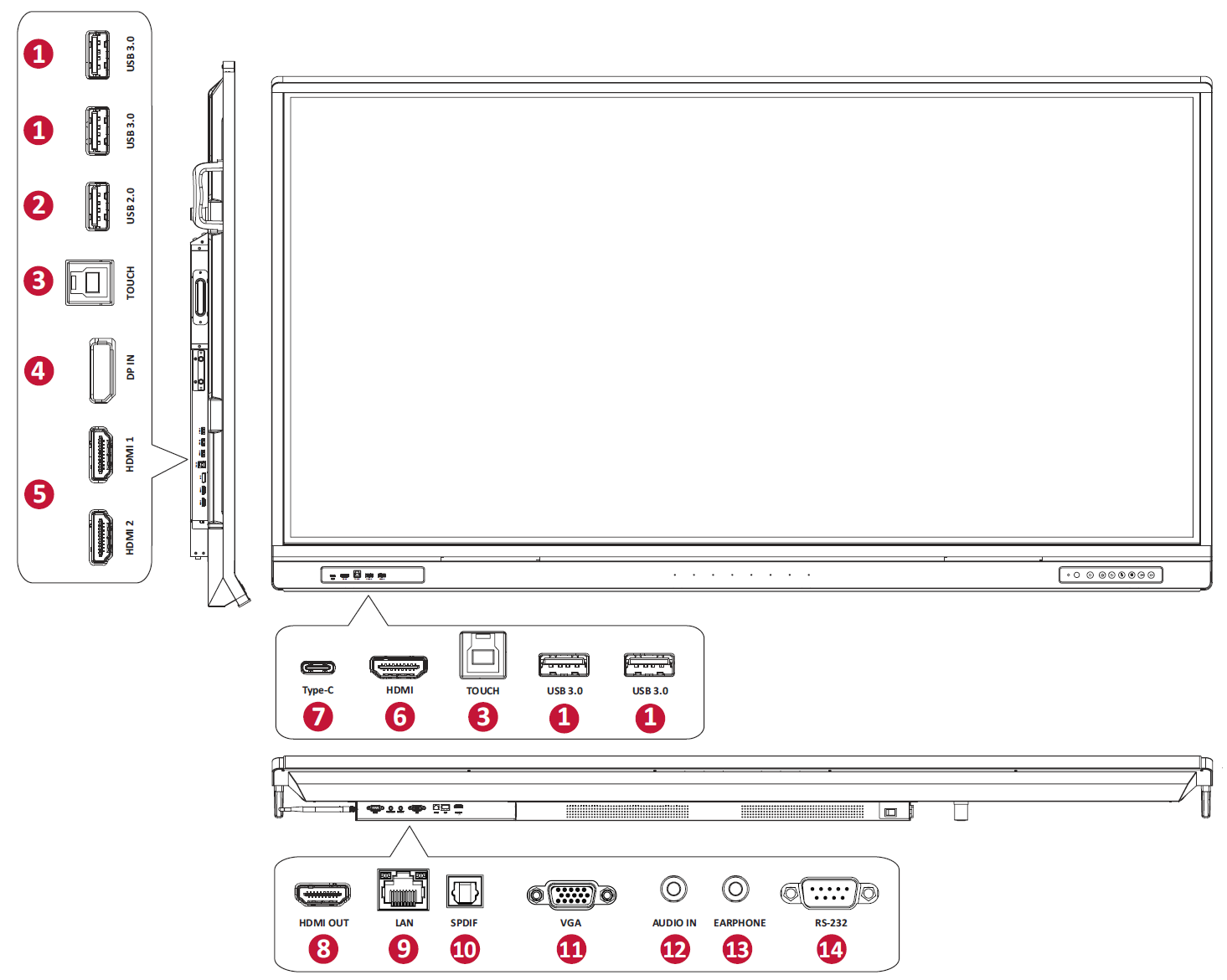
Su IFP52 viene con varios paneles de entrada/salida (E/S). Los puertos de estos paneles ofrecen diferentes formas de conectar dispositivos externos por cable.

|
Puerto |
Función |
|---|---|---|
| 1 | USB 3.0 | Conecte dispositivos USB como un disco duro, teclado, mouse, etc. Cambia automáticamente entre las fuentes de entrada de PC y ViewBoard . |
| 2 | USB 2.0 | Conecte dispositivos USB como un disco duro, teclado, mouse, etc. ( 5 V CC/0,5 A) |
| 3 | TOUCH |
|
| 4 | DisplayPort ENTRADA | Entrada DisplayPort para conectar a una PC con salida DisplayPort. |
| 5 | HDMI 1/2 | entrada de alta definición; conectar a una PC (u otro dispositivo) con una salida HDMI. |
| 6 | HDMI | entrada de alta definición; conectar a una PC (u otro dispositivo) con una salida HDMI. |
| 7 | USB tipo C | entrada USB tipo C; conectar a una PC con una salida USB Tipo-C. |
| 8 | SALIDA HDMI | Conéctese a dispositivos con una función de entrada HDMI. Soporta 1080p y 4K@60Hz. |
| 9 | LAN | Interfaz de conexión a Internet estándar RJ45 (10M/100M/1000M). Este puerto de red se utiliza para las fuentes de entrada ViewBoard , Type-C y PC con ranura. |
| 10 | SPDIF | Sonido multicanal a través de señales ópticas. |
| 11 | VGA | Entrada de video de computadora externa. |
| 12 | AUDIO EN | Entrada de audio de computadora externa. |
| 13 | AURICULAR | Salida de audio a un altavoz/auricular externo. |
| 14 | RS-232 | Interfaz de serie; Se utiliza para la transferencia mutua de datos entre dispositivos. |
Aprender más
 Inicio